A dedicated NS-3 Module for IEEE 802.22 standard
Little bit of ranting
During my MS Thesis work in 2015, I researched on the resource (subchannel, power) scheduling problem in wireless regional area network (WRAN). IEEE 802.22 standard is considered as the first wireless standard based on CR technology for WRAN. I worked under the supervision of professor Dr. Md. Abdur Razzaque in the GNR group of CSEDU. We used NS-3 for assessing and monitoring different aspects of network models. While trying to implement a WRAN environment in NS-3, NS-3 betrayed us by having no dedicated module for WRAN. So what, we wrote our own WRAN module in NS-3.Rolling in the IEEE 802.22
Now, I am going to dive deeper into the IEEE 802.22, not much deeper, just what is needed to know for our WRAN module. For more enthusiast readers, I highly encourage to go through this official IEEE draft.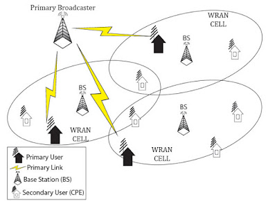 |
| Figure 1 : IEEE 802.22 network architecture |
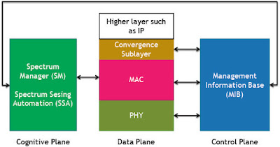 |
| Figure 2 : IEEE 802.22 reference architecture |
Data Plane
It consists of the physical layer (PHY), the medium access control (MAC) layer and the convergence
sublayer (CS). Service Access Points (SAPs) are added in between these layers to allow modularization of the system where different components may be disjointed and/or from different vendors. The Data & Control/Management plane of the MAC is comprised of three sublayers: service-specific CS, the MAC Common Part sublayer (CPS), and the security sublayer. The MAC Common Part sublayer shall provide the core MAC functionality of system access, connection establishment, and connection maintenance.
Management/Control Plane
The management/control plane consists of the Management Information Base (MIB). The MIB primitives is used for system configuration, monitoring statistics, notifications, triggers, CPE and session management, Radio Resources Management (RRM), communication with the database service, spectrum sensing and geolocation reporting, etc.
Cognitive plane
The cognitive plane is composed of the Spectrum Sensing Function (SSF), the Geolocation (GL) function, the Spectrum Manager/Spectrum Sensing Automaton (SM/SSA) and a dedicated security sublayer 2. The SSF implements spectrum sensing algorithms and the GL module provides the information to determine the location of the IEEE 802.22 device (BS or CPE). The key functionalities of Spectrum Manager covers - maintaining spectrum availability Information, channel classification and selection, channel set management, making channel move decision, self-coexistence, etc.
All about the NS-3
NS-3 has 4 basic abstraction level for maintaining different network entities.- Node: A node is simply a computing device or a network host that is connected to the network. At the beginning of writing NS-3 codes, one or more node should be created, in which network devices like peripheral cards will be added followed by implementing protocol stacks and different applications. NS-3 provides a basic c++ class - Node, having basic methods to control the node during simulation.
- Application: An application holds the user program or algorithm which generates some activity to be simulated in the network environment. NS-3 provides a basic c++ class - Application, having basic methods for controlling an application. It can be extended to write customized user application to monitor in the network environment.
- Channel: A channel is an entity over which the data will be flowed. A basic c++ class - Channel provides methods for typical channel handling. It can be extended and customized by users according to their needs to match the real work wired or wireless channels.
- Net Device: Net devices resembles the network device driver that will be attached to a Node. It provides an abstraction of Network Interface Card (NIC) with device driver to control the NIC. The NetDevice c++ basic class contains the basic functionality of an NIC card.
- Topology Helper: In addition to the above 4 components, topology helper class provides convenient way to handle these components. For example, a NetDevice will always connect to a Node, one or more Channel are assigned to a NetDevice with IP address, mac address, mobility models, etc, and at last an Application is attached to it. These common procedures are handled collectively by the topology helper.
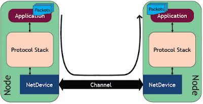 |
| Figure 3 : NS-3 basic components in operation |
Something like - The WRAN Module
No dedicated module for the IEEE 802.22 standard or wireless regional area networks (WRAN) is available in NS-3 (At least as of during our research work in the July, 2015). There is a module for WiMAX which is based on IEEE 802.16 standard for broadband wireless access (BWA) networks. Some similarities can be found between the core functionalities of WiMAX and WRAN - in fact, IEEE 802.22 MAC is totally based on IEEE 802.16 MAC. The key differences between them have been listed in the table.
| IEEE 802.22 (WRAN) | IEEE 802.16 (WiMAX) | |
|---|---|---|
| Frequency Usage | 54 to 862 MHz | 2 to 11 GHz |
| Air Interface | OFDMA | OFDMA, Single Carrier. |
| OFDMA Channel Profile (Bandwidth) | 6,7,8 (according to regulatory domain) | 28, 20, 17.5, 14, 10, 8.75, 7, 3.5, 1.25 |
| MAC frame structure | Superframe-frame. Frame Size: 10ms | No Superframe. Frame Size: 2,5,10,20 ms |
| Self-Coexistence | DRRO, AODCC etc. | Master frame Assignment |
| Data Rate | 27Mbps (Average) 75Mbps (Aggregate) | 54Mbps (Average) 75Mbps (Aggregate) |
| Distance | 30-100 km | 4 km or less |
In developing the WRAN module, we cloned the WiMAX module and changed respective models with appropriate specification of the IEEE 802.22 standards. In Figure. 4, the basic architecture for the developed WRAN module is presented. Note that, only key models is used to depict the architecture in this figure. We also had to design a separate cognitive plane - depicted in Figure. 5, since the WiMAX module doesn’t have any cognitive plane by design. The design of the cognitive plane is based on the cognitive radio extension for NS-3 developed by Kaushik et. al. It was developed over wifi channel, We modified it to run over our custom OFDMA based TV channels. This cognitive plane is used by WranPhy to choose the next channel for communication.
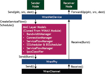 |
| Figure 4 : WRAN Module Architecture |
Here, the WranNetDevice model creates a transparent layer between the application layer and the MAC layer. Its responsibility is to define downlink and uplink frames, generate service flow and schedule packets to sends via lower level MAC layer related models. The WranServiceFlowManager creates and handles services for the communication. Depending on the services needed to provide, it uses WranSSScheduler and WranBSScheduler for scheduling packets between net devices. These schedulers are also responsible for creating MAC massages and send them through WranPhy using different types of uplink schedulers - WranUplinkSchedulerSimple, WranUplinkSchedulerRtps, WranUplinkSchedulerMBQoS.
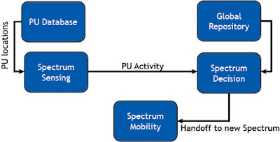 |
| Figure 5 : Cognitive Plane Architecture |
The WranPhy creates a virtual physical layer by defining channel, frequency and bandwidth. A default SimpleOfdmWranPhy with SimpleOfdmWranChannel extension is provided to create OFDMA medium; since, OFDMA is the default air interface for the IEEE 802.22 standards. Upon receiving packets, WranPhy sends bursts message (collection of packets) to respective net devices. One communication link cycle ends by forwarding packets to the destination node by net
devices.
Hello from the WRAN Module
We developed our module for NS-3 version 3.26 (it was the latest version during our research). It can be downloaded from the official address linked here. We installed it in Ubuntu 14.10. To run NS-3, some prerequisite packages are needed to be installed in the system. In Ubuntu system the following commands can be used to install them,- C++
apt-get install gcc g++ python
- Python (release)
apt-get install gcc g++ python python-dev
- Python (development)
apt-get install mercurial python-setuptools git
- qt4 development tools for NetAnim
apt-get install qt4-dev-tools libqt4-dev
A detailed instruction for installation can be found here. When the installation is successful, you can build and configure NS-3 using waf tools as follows:
./waf clean
./waf configure --build-profile=optimized --enable-examples --enable-tests
After completion of configuration, run and test the hello-simulator as follows:
./waf --run hello-simulator
If everything goes perfectly, the following output will depict that your system is ready to run, test and do experiments in NS-3.
Hello Simulator
Our newly developed WRAN module included NS-3 codebase can be downloaded from this github source-base. Usage of the WRAN module is depicted by this sample code. A helper class WranHelper is developed to ease out the configurations. The following codes will read the primary users repository file and create a Repository for later use.
Ptr<pumodel> puModel = CreateObject<pumodel>();
std::string map_file = "map PUs multiple.txt";
puModel->SetPuMapFile((char *)map_file.c_str());

Ptr<repository> repo = CreateObject<repository>();
Then create NodeContainer for holding the BS and SS nodes as follows:
NodeContainer ssNodes;
NodeContainer bsNodes;

ssNodes.Create (mxSS);
bsNodes.Create(mxBS);
Now, use WranHelper class to create net devices and store those in net device containers.
WranHelper wran;
NetDeviceContainer ssDevs , bsDevs;
WranHelper::SchedulerType scheduler = WranHelper::SCHED_TYPE_SIMPLE;

ssDevs = wran.Install (repo, puModel, ssNodes,
            WranHelper::DEVICE_TYPE_SUBSCRIBER_STATION,
            WranHelper::SIMPLE_PHY_TYPE_OFDM,
            scheduler);

bsDevs = wran.Install (repo, puModel, bsNodes,
            WranHelper::DEVICE_TYPE_BASE_STATION,
            WranHelper::SIMPLE_PHY_TYPE_OFDM,
            scheduler);
Then we set the propagation loss model as FRIIS propagation model and modulation type as QAM16:
wran.SetPropagationLossModel(SimpleOfdmWranChannel::FRIIS_PROPAGATION);
Ptr<WranSubscriberStationNetDevic> ss[mxSS];
for(int i=0; i<mxss; i++){
    ss[i] = ssDevs.Get(i)->GetObject<WranSubscriberStationNetDevic>();
    ss[i]->SetModulationType(WranPhy::MODULATION_TYPE_QAM16_12);
}
After that, we install the InternetStackHelper and assign IP addresses to nodes as follows:
InternetStackHelper stack;
stack.Install(bsNodes);
stack.Install (ssNodes);

Ipv4AddressHelper address;
address.SetBase ("10.1.1.0" , "255.255.255.0");

Ipv4InterfaceContainer SSinterfaces = address.Assign(ssDevs);
Ipv4InterfaceContainer BSinterface = address.Assign(bsDevs);
Then, after installing any suitable mobility models to nodes, run the simulation by following commands from the terminal:
./waf --run "wran"
Considering all log components disabled, after running the program the following output should be shown in the terminal:
Starting simulation . . . . .
Done.
The source code for this WRAN module and all related commits can be found in this github repository. This is just a basic implementation of the module. Although It cannot handle all the features proposed by the IEEE 802.22, it provides a basic layout upon which different network features of 802.22 can be implemented and tested. For any question, query, feedback, clarification, correction, or update - feel free to contact me anytime.

